What is Kaplan Turbine? Diagram and Working Principles Linquip
One of the most important milestones in the history of hydropower is the invention of the Kaplan turbine. It is a machine stemming from the Francis turbine, which Viktor Kaplan was originally trying to improve. However, it gradually developed into the creation of a completely new solution of an impeller with an axial flow rate and adjustable blades. The first patent relating to the new.
Kaplan Turbine 3d Animation and Design YouTube
The vertical configuration of the Kaplan turbine allows for larger runner diameters (above 10 m) and increased unit power, as compared to Bulb Turbines. Our Kaplan turbines also keep the environment in mind. Engineered with a "fish-friendly" structure, to improve the survival rate of migrating species, and water-lubricated bearings and water.
Kaplan spiraltypekaplanturbine Hydrohrom s.r.o.
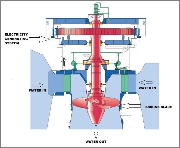
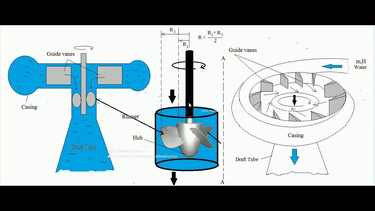
Kaplan turbine works on the principle of the axial flow reaction. In an axial flow turbine, the fluid moves by the impeller in a direction parallel to the impeller's axis of rotation. A Kaplan turbine works in the following way: First of all, the water introduces into the volute/scroll casing from the penstock.
6 Österreichische Erfindungen, die unsere Welt mächtig beeinflusst
The Kaplan turbine is a specialized water turbine designed to generate electricity from flowing water, especially in low-head, high-flow environments. Introduced in 1913 by its namesake, Viktor Kaplan, this turbine has since carved a niche for itself in the world of renewable energy [1]. At its core, the Kaplan turbine working principle.
Kaplan Spiraltypekaplanturbinefr Hydrohrom s.r.o.
7.3.1.2.2 Kaplan turbine. Kaplan turbine is a complete reaction turbine that works based on the lift force generated on the impeller blades due to its aerofoil shape [29]. The working process of the Kaplan turbine is similar to the propeller-type turbine along with adjustable runner blades so that it can work smoothly at vortices and shocks.

Kaplan Turbine Zeco Hydropower
The Kaplan turbine was an evolution of the Francis turbine. Its invention allowed efficient power production in low- head applications which was not possible with Francis turbines. The head ranges from 10 to 70 metres (33 to 230 ft) and the output ranges from 5 to 200 MW. Runner diameters are between 2 and 11 metres (6 ft 7 in and 36 ft 1 in).
What is Kaplan Turbine? Diagram and Working Principles Linquip
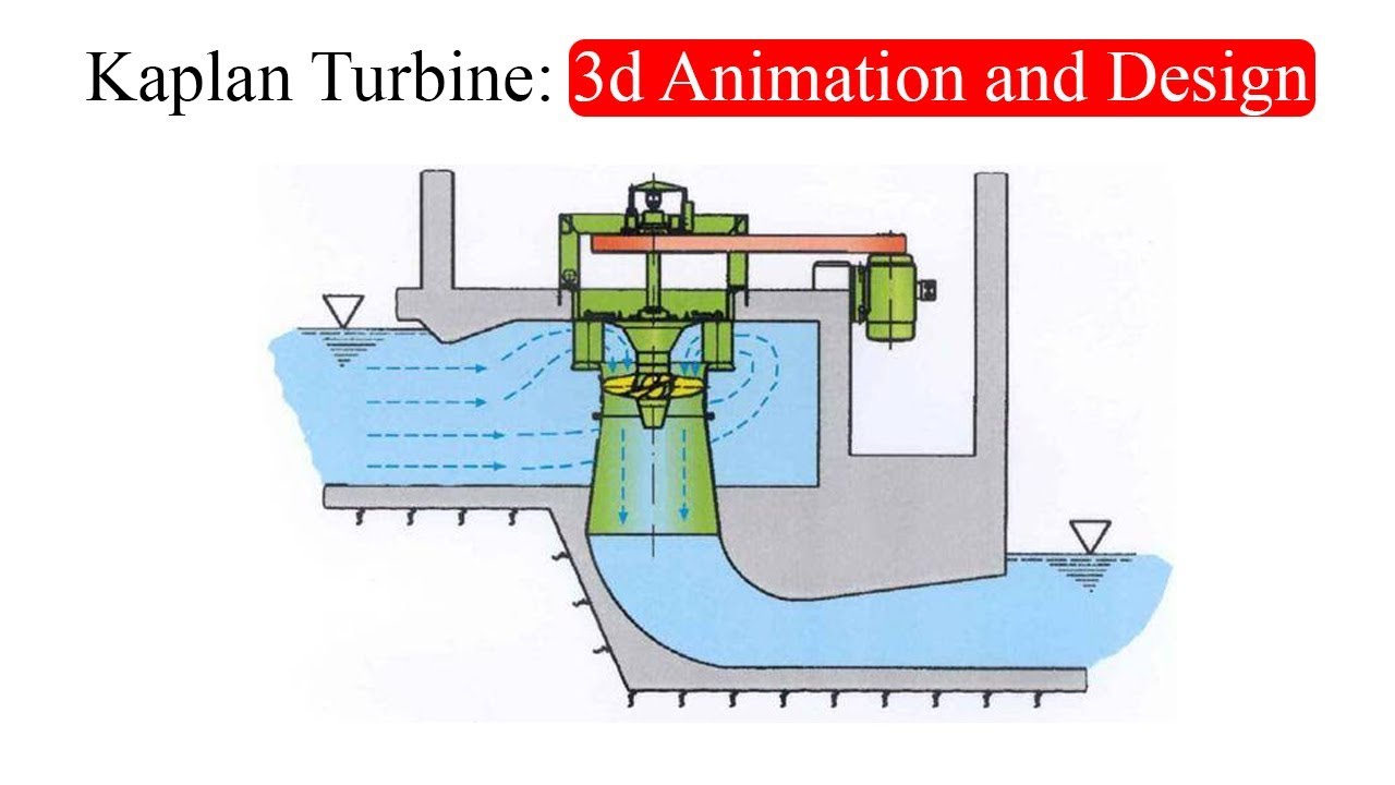
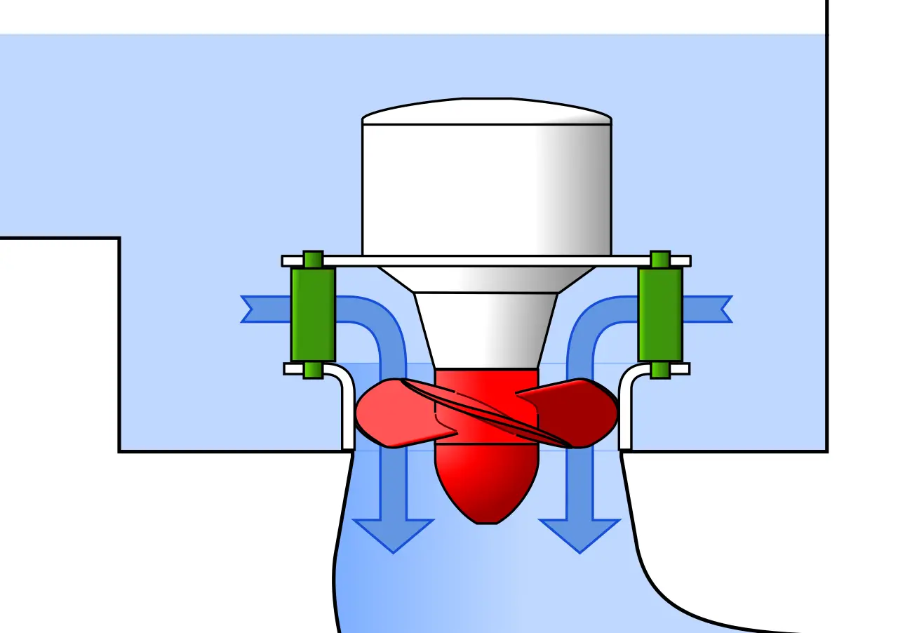
The commonest orientation currently being installed in the UK (at least by Renewables First) is vertical axis. Vertical-axis Kaplan's have the advantage of requiring the smallest footprint or land-take. A typical layout is shown in Figure 4. The Kaplan turbine is built into the concrete structure, with the inlet volute (basically a snail.
Kaplan spiraltypekaplanturbine Hydrohrom s.r.o.
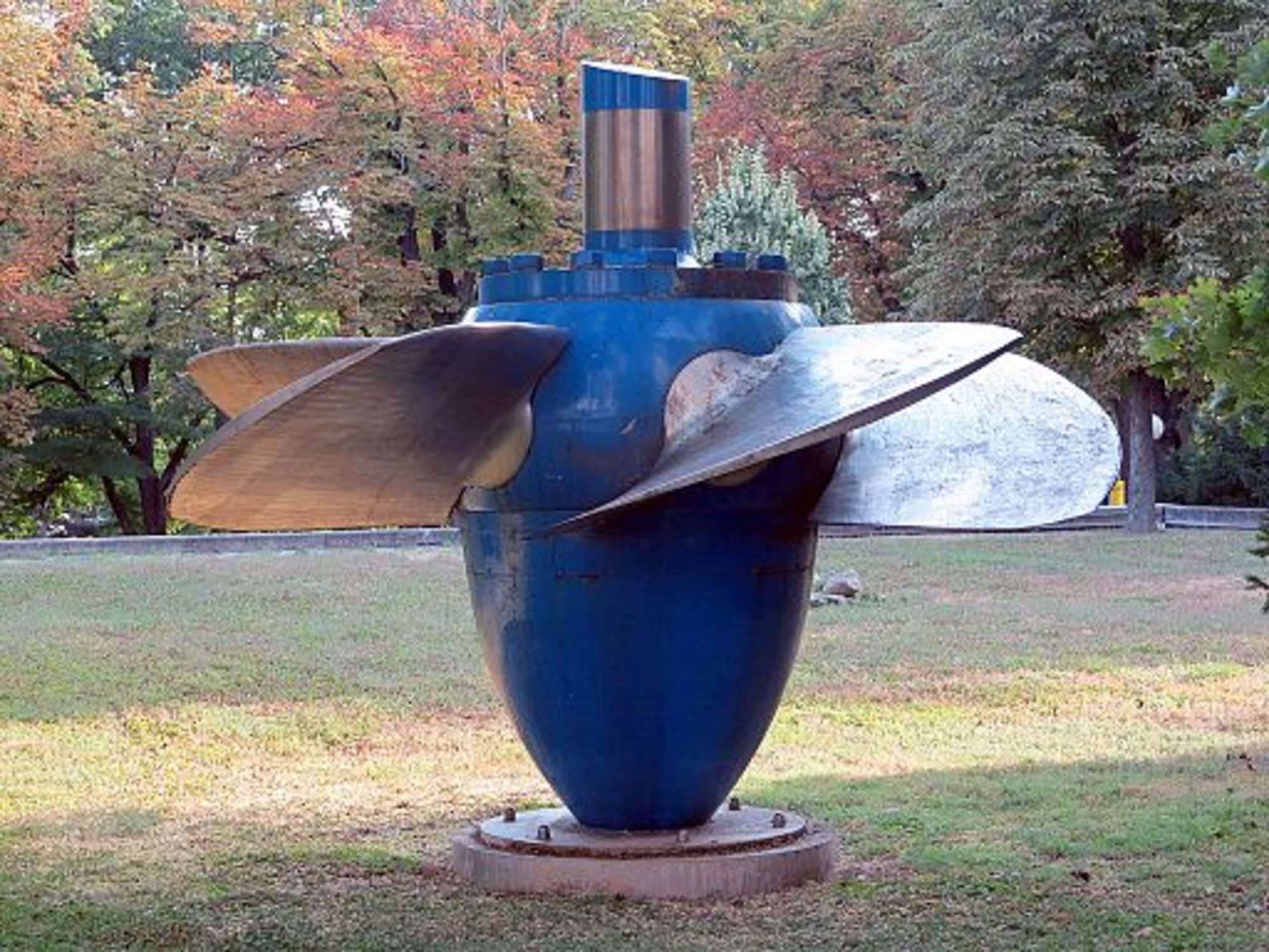
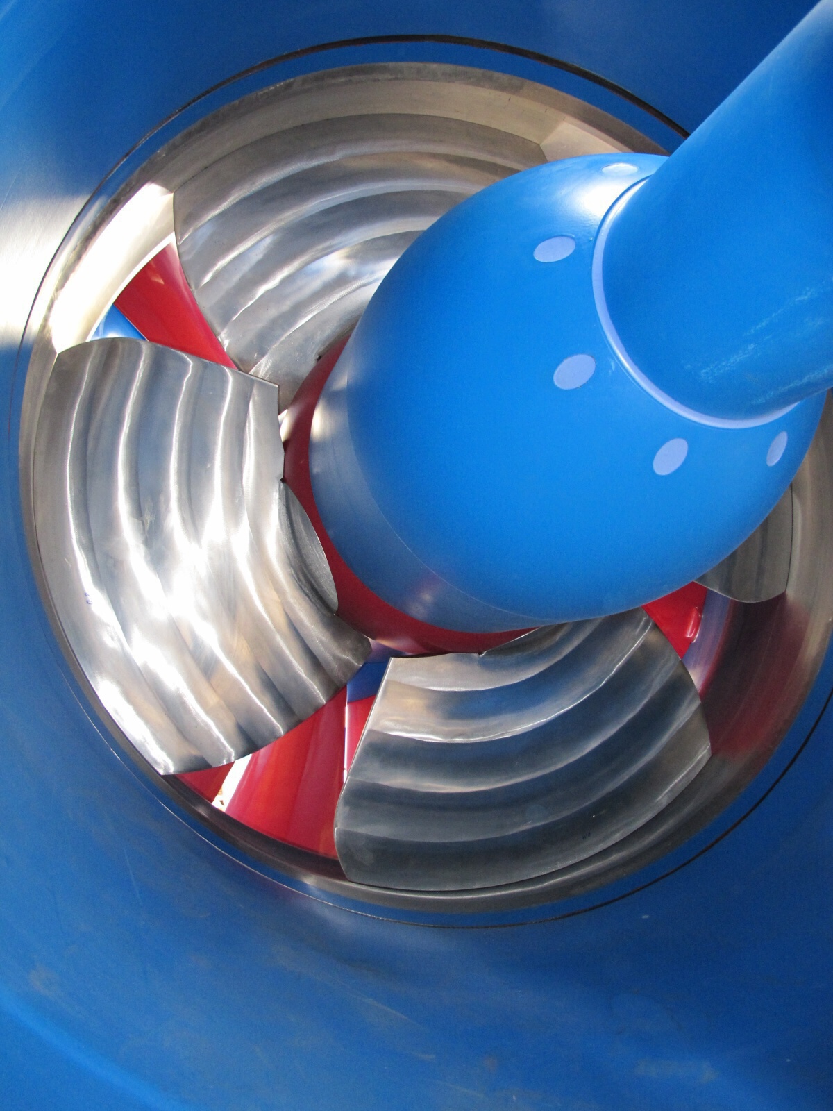
A widely used turbine type is the Kaplan Turbine, looking very much like a giant propeller. Its efficiency is very high, it can "capture" over 90% of the kinetic energy of the outlet stream. Today, however, another turbine type is taking over - namely, the Francis Turbine (Fig. 5.11). It was invented 170 years ago by a Massachusetts.
Kaplan Turbine ER3I
A reaction turbine is one sort of turbine that generates torque by reacting to the weight or pressure of a fluid. The operation of reaction turbines can be described by Newton's third law of motion (i.e. action and reaction are balanced and reverse). The Kaplan turbine is a full reaction turbine that operates by generating lift on the.

Kaplan sktypesshapedoubleregulatedhorizontalkaplanturbine
A Kaplan turbine is a type of propeller hydro turbine (specifically a reaction turbine) used in hydroelectric plants.Water flows both in and out of Kaplan turbines along its rotational axis ().What makes Kaplan turbines special is the blades can change their angle on demand to maintain maximum efficiency for different flow rates of water. Water flowing through a Kaplan turbine loses pressure.
Kaplan Turbine Working , Power and Efficiency. YouTube
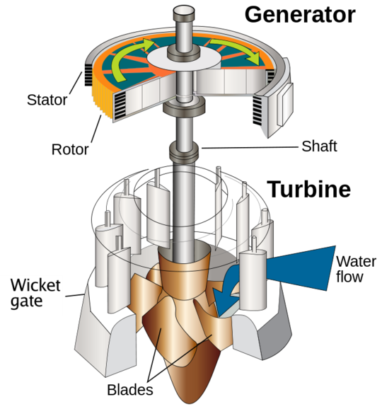
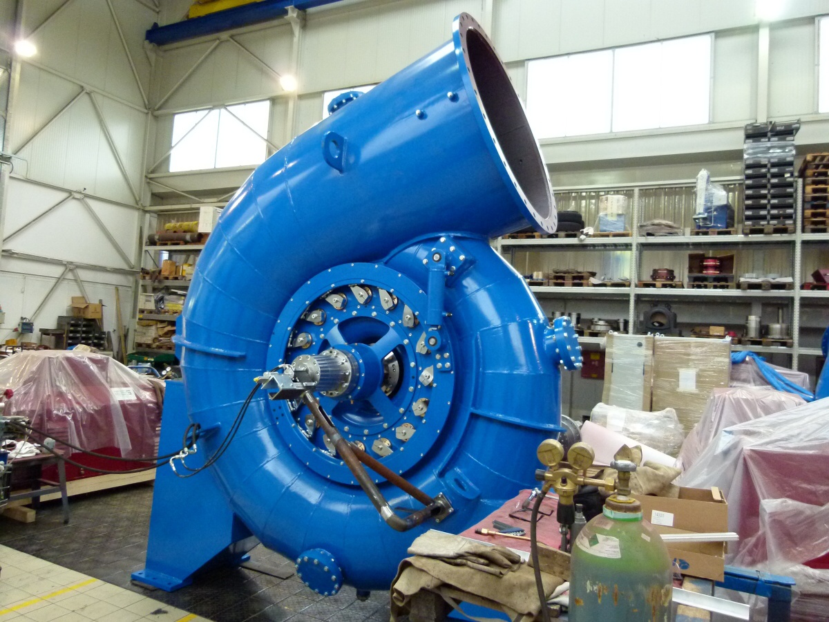
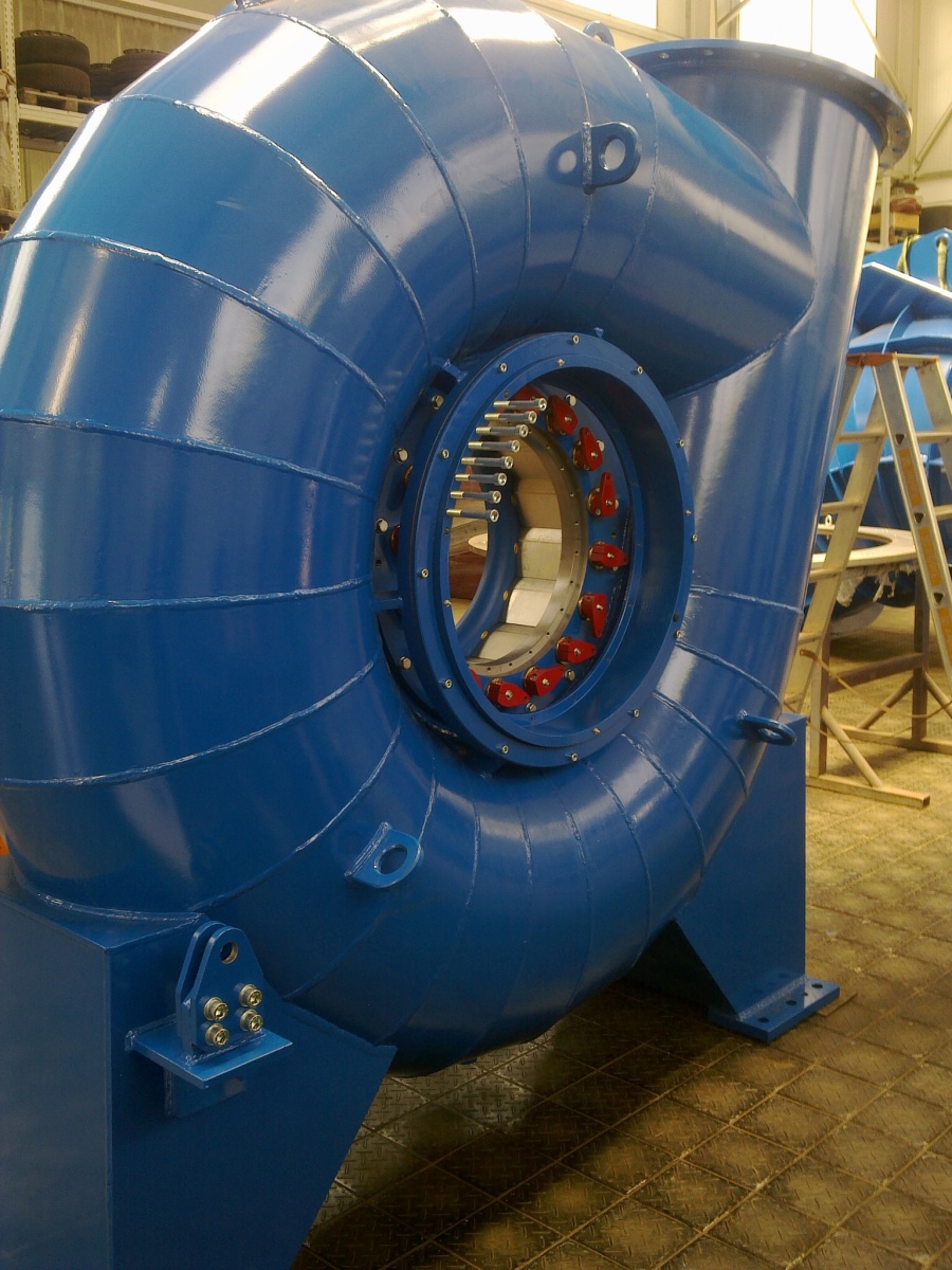
Main Components of Kaplan Turbine. The main parts of Kaplan Turbine are, 1. Scroll Casing. It is a spiral type of casing that has decreasing cross section area. The water from the penstocks enters the scroll casing and then moves to the guide vanes where the water turns through 90° and flows axially through the runner.
What is Kaplan Turbine and How It Works? Mechanical Booster
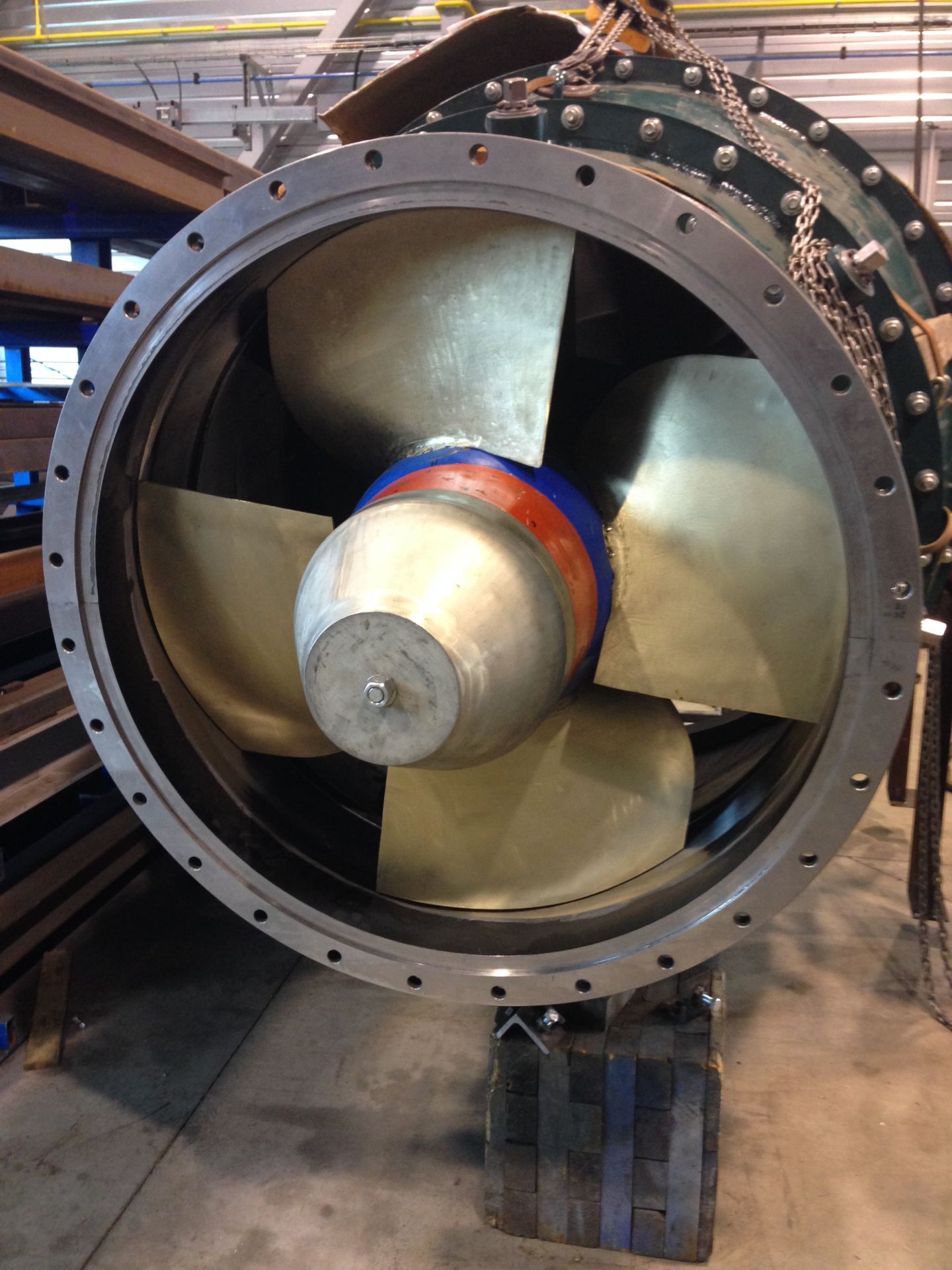
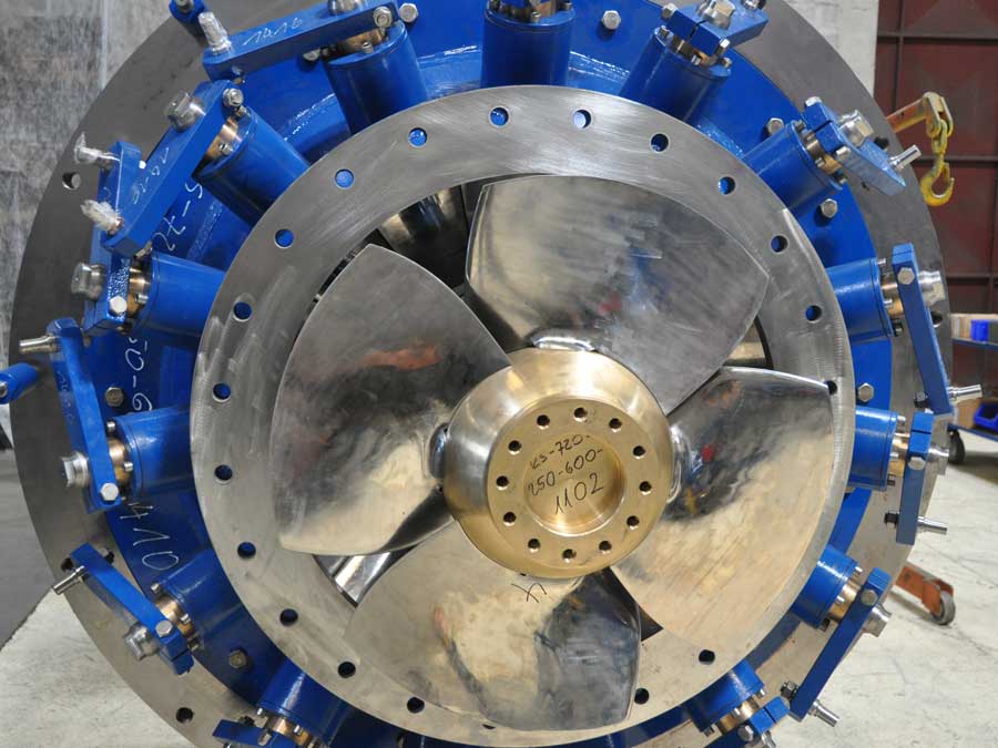
The Kaplan turbine is a hydraulic turbine that uses small gradients, up to a few tens of meters, but with a massive flow of water rates, from 200/300 m³ / s. Kaplan turbines are widely used throughout the world in hydropower plants for electrical power production. Constructively, this hydraulic turbine is a propeller, where the blades can be.

Kaplan Hydro Turbine S type, P=300kW YouTube
Definition of Kaplan Turbine. Kaplan turbine is a reaction turbine that is used for low heads and requires a large quantity of water for developing a large amount of power. Kaplan turbine runs faster. High efficiency. It is located between the high-pressure water source and the low-pressure water exit.
SIAPRO Kaplan turbines design and production
The Kaplan Turbine is an evolved version of the Francis Turbine, and is used in mostly low head sites where the Francis turbine was less efficient. The Kaplan Turbine uses a specially designed propeller blade that is similar to the design of a propellor of an airplane. The main disadvantage of a Kaplan turbine is that they are very expensive to.
Kaplan sktypesshapedoubleregulatedhorizontalkaplanturbine
Although the power output increases with the inlet velocity the efficiency of the runner reaches a maximum of 93.01% with an inlet velocity of 7.64 m.s-1 and then starts to decrease. The original theoretical design in CFD shows a maximum efficiency of about 51-52% (exactly 50.98%), somewhere between 7.64 and 8 m.s-1.
Kaplan turbine Energy Education
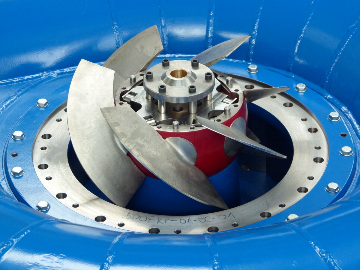
Kaplan S Turbine; Our Kaplan turbines are equipped with 3 to 6 blades depending on the type and head and have efficiencies of up to 93%. If possible, a direct coupling of the generator and the Kaplan turbine is preferable. Otherwise, power transmission can be realized by using flat belts or gearboxes, depending on the performance class and.
